A couple of months ago my friend Chris told me over a beer the problems he was having with accurately measuring the speed of a toy car over a track for a STEM project. At that time I was (and still am) looking for excuses to be involved in some technology fun outside of work. So not knowing much about possible sensors, I theorised with him that an Arduino could do a good job at measuring the speed rather accurately.
After some short research, I concluded that the so called beam-break sensors (i.e. a pair of sensors formed by an IR LED and an IR photo-transistor as a receiver) would probably be the best way to implement this. I also added a LCD to the mix so that the speed could be displayed straight away. The picture below roughly explains the idea.
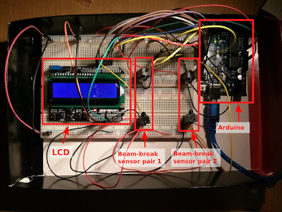
For the demonstrator I used an Arduino UNO, a couple of beam-brake sensors for Adafruit, a cheap LCD board, a couple of breadboards and a few jumper wires. I actually didn't use the battery pack, but you can use 4 AAA rechargeable Ni-MH batteries to provide roughly the 5 volts required for the sensors, so that you don't have so pass so many wires from one side to the other side of the track.
The HW setup is rather simple. First connect the ground and power from the Arduino to the breadboard for a common bus. Connect the 4 sensors there. One sensor of each pair (the receiver) also need a digital pin so that we can tell if the beam has been broken or not.
The LCD is a bit more complicated. Apart from power and ground, it needs 6 digital pins to work. We just need to make sure that these pins are connected to the right places in the LCD board. The pins in the LCD board that require connection are shown in the figure below, labelled as 'D7 to D4' and 'D9 & D8' . These are 6 consecutive pins starting from the 5th pin in the top-left corner (i.e. the 5th pin starting from the top-left corner is D4, the next downwards is D5, and so on). The reason why there seems to be a gap between pins D7 and D8 is because there is a gap in the physical pin of the LCD board (so it can slot on top of the Arduino pins). The A0 pin is used to drive the buttons of the board and should be connected to an analog pin in the Arduino.
In terms of SW, we need to use the LiquidCrystal library to drive the LCD, and make sure that we initialise the pins to the right ones, as connected to the Arduino. We also need to set the digital pins of the sensors as INPUT, and turn on the internal pullup resistor to make sure the default value is HIGH, i.e. beam not broken. After setup(), in the loop section, we need to:
I won't put all the code here, so I leave it as an exercise for the reader. It is not a difficult job if you have some experience with the Arduino. I do have a full user guide which I might upload at some point.
After some short research, I concluded that the so called beam-break sensors (i.e. a pair of sensors formed by an IR LED and an IR photo-transistor as a receiver) would probably be the best way to implement this. I also added a LCD to the mix so that the speed could be displayed straight away. The picture below roughly explains the idea.
The HW setup is rather simple. First connect the ground and power from the Arduino to the breadboard for a common bus. Connect the 4 sensors there. One sensor of each pair (the receiver) also need a digital pin so that we can tell if the beam has been broken or not.
The LCD is a bit more complicated. Apart from power and ground, it needs 6 digital pins to work. We just need to make sure that these pins are connected to the right places in the LCD board. The pins in the LCD board that require connection are shown in the figure below, labelled as 'D7 to D4' and 'D9 & D8' . These are 6 consecutive pins starting from the 5th pin in the top-left corner (i.e. the 5th pin starting from the top-left corner is D4, the next downwards is D5, and so on). The reason why there seems to be a gap between pins D7 and D8 is because there is a gap in the physical pin of the LCD board (so it can slot on top of the Arduino pins). The A0 pin is used to drive the buttons of the board and should be connected to an analog pin in the Arduino.
- Read the status of the data pins of the beam-break sensors, to see if they have been broken or not.
- If the were broken, record the time at which it happened (using millis()).
- If the breaking of the beams happened in the right order, calculate the speed (for this, we obviously need to know the distance between both pairs of sensors).
- Output our calculation to the LCD.
- Output our calculation to the serial port (for debugging).
- Prepare the variables to run the 'loop' section again
I won't put all the code here, so I leave it as an exercise for the reader. It is not a difficult job if you have some experience with the Arduino. I do have a full user guide which I might upload at some point.
Happy Hacking.


